[tabby title=”Video Walkthrough”]
Learn the basics of controlling objects with your Smartphone through Bluetooth!
[tabby title=”Parts List”]
- A Bluetooth Capable Smartphone (I’ll be using an Android).
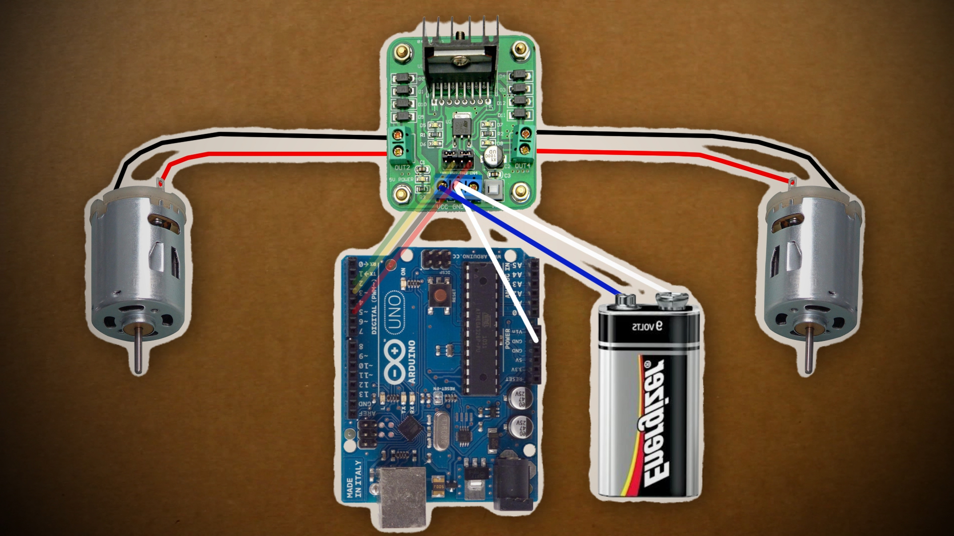
- An Arduino ($10.99)
- An Arduino Bluetooth Module ($6.45)
- An RC Car (this is the one I used) ($5.00 – $30.00)
- An H-Bridge motor controller ($9.69)
- A Wires ($4.20)
- A 9v Battery ($2.00)
TOTAL COST: ~$30.00
[tabby title=”Step 1″]
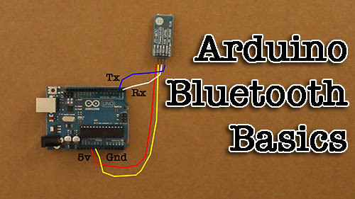
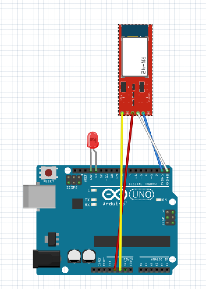
- To get started on adding bluetooth to the Arduino, you can watch my Arduino Bluetooth Basics Tutorial
-
For a wiring diagram, you can reference my Fritzing sketch. (You need to download Fritzing
in order t. view this.)
[tabby title=”Step 2″]
Software
Android
- To find your bluetooth’s MAC address, a good program to use is called Ardudroid on the Google Play store.
- To control the car, Tolik777 has created a great app that you can download from here and install on your Anrdoid device.
Arduino
- The first thing you need to to is download the Arduino software for your computer.
- Then you need to copy this code to a new sketch and upload it to your Arduino device. Code provided by
#include "EEPROM.h"

#define D1 2          // direction of motor rotation 1
#define M1 3          // PWM left motor
#define D2 4          // direction of motor rotation 2
#define M2 5          // PWM right motor
#define HORN 13       // additional channel 1
//#define autoOFF 2500  // milliseconds after which the robot stops when the connection

#define cmdL 'L'      // UART-command for left motor
#define cmdR 'R'      // UART-command for right motor
#define cmdH 'H'      // UART-command for additional channel (for example Horn)
#define cmdF 'F'      // UART-command for EEPROM operation
#define cmdr 'r'      // UART-command for EEPROM operation (read)
#define cmdw 'w'      // UART-command for EEPROM operation (write)

char incomingByte;    // incoming data

char L_Data[4];       // array data for left motor
byte L_index = 0;     // index of array L
char R_Data[4];       // array data for right motor
byte R_index = 0;     // index of array R
char H_Data[1];       // array data for additional channel
byte H_index = 0;     // index of array H
char F_Data[8];       // array data for  EEPROM
byte F_index = 0;     // index of array F
char command;         // command

unsigned long currentTime, lastTimeCommand, autoOFF;

void setup() {
  Serial.begin(9600);       // initialization UART
  pinMode(HORN, OUTPUT);    // additional channel
  pinMode(D1, OUTPUT);      // output for motor rotation
  pinMode(D2, OUTPUT);      // output for motor rotation
  /*EEPROM.write(0,255);
  EEPROM.write(1,255);
  EEPROM.write(2,255);
  EEPROM.write(3,255);*/
  timer_init();             // initialization software timer
}

void timer_init() {
  uint8_t sw_autoOFF = EEPROM.read(0);   // read EEPROM "is activated or not stopping the car when losing connection"
  if(sw_autoOFF == '1'){                 // if activated
    char var_Data[3];
    var_Data[0] = EEPROM.read(1);
    var_Data[1] = EEPROM.read(2);
    var_Data[2] = EEPROM.read(3);
    autoOFF = atoi(var_Data)*100;        // variable autoOFF ms
  }
  else if(sw_autoOFF == '0'){
    autoOFF = 999999;
  }
  else if(sw_autoOFF == 255){
    autoOFF = 2500;                      // if the EEPROM is blank, dafault value is 2.5 sec
  }
  currentTime = millis();                // read the time elapsed since application start
}

void loop() {
  if (Serial.available() > 0) {          // if received UART data
    incomingByte = Serial.read();        // raed byte
    if(incomingByte == cmdL) {           // if received data for left motor L
      command = cmdL;                    // current command
      memset(L_Data,0,sizeof(L_Data));   // clear array
      L_index = 0;                       // resetting array index
    }
    else if(incomingByte == cmdR) {      // if received data for left motor R
      command = cmdR;
      memset(R_Data,0,sizeof(R_Data));
      R_index = 0;
    }
    else if(incomingByte == cmdH) {      // if received data for additional channel
      command = cmdH;
      memset(H_Data,0,sizeof(H_Data));
      H_index = 0;
    }
    else if(incomingByte == cmdF) {      // if received data for EEPROM op
      command = cmdF;
      memset(F_Data,0,sizeof(F_Data));
      F_index = 0;
    }
    else if(incomingByte == '\r') command = 'e';   // end of line
    else if(incomingByte == '\t') command = 't';   // end of line for EEPROM op

    if(command == cmdL && incomingByte != cmdL){
      L_Data[L_index] = incomingByte;              // store each byte in the array
      L_index++;                                   // increment array index
    }
    else if(command == cmdR && incomingByte != cmdR){
      R_Data[R_index] = incomingByte;
      R_index++;
    }
    else if(command == cmdH && incomingByte != cmdH){
      H_Data[H_index] = incomingByte;
      H_index++;
    }
    else if(command == cmdF && incomingByte != cmdF){
      F_Data[F_index] = incomingByte;
      F_index++;
    }
    else if(command == 'e'){                       // if we take the line end
      Control4WD(atoi(L_Data),atoi(R_Data),atoi(H_Data));
      delay(10);
    }
    else if(command == 't'){                       // if we take the EEPROM line end
      Flash_Op(F_Data[0],F_Data[1],F_Data[2],F_Data[3],F_Data[4]);
    }
    lastTimeCommand = millis();                    // read the time elapsed since application start
  }
  if(millis() >= (lastTimeCommand + autoOFF)){     // compare the current timer with variable lastTimeCommand + autoOFF
    Control4WD(0,0,0);                             // stop the car
  }
}

void Control4WD(int mLeft, int mRight, uint8_t Horn){

  bool directionL, directionR;      // direction of motor rotation L298N
  byte valueL, valueR;              // PWM M1, M2 (0-255)

  if(mLeft > 0){
    valueL = mLeft;
    directionL = 0;
  }
  else if(mLeft < 0){
    valueL = 255 - abs(mLeft);
    directionL = 1;
  }
  else {
    directionL = 0;
    valueL = 0;
  }

  if(mRight > 0){
    valueR = mRight;
    directionR = 0;
  }
  else if(mRight < 0){
    valueR = 255 - abs(mRight);
    directionR = 1;
  }
  else {
    directionR = 0;
    valueR = 0;
  }

  analogWrite(M1, valueL);            // set speed for left motor
  analogWrite(M2, valueR);            // set speed for right motor
  digitalWrite(D1, directionL);       // set direction of left motor rotation
  digitalWrite(D2, directionR);       // set direction of right motor rotation

  digitalWrite(HORN, Horn);           // additional channel
}

void Flash_Op(char FCMD, uint8_t z1, uint8_t z2, uint8_t z3, uint8_t z4){

  if(FCMD == cmdr){           // if EEPROM data read command
    Serial.print("FData:");       // send EEPROM data
    Serial.write(EEPROM.read(0));     // read value from the memory with 0 address and print it to UART
    Serial.write(EEPROM.read(1));
    Serial.write(EEPROM.read(2));
    Serial.write(EEPROM.read(3));
    Serial.print("\r\n");         // mark the end of the transmission of data EEPROM
  }
  else if(FCMD == cmdw){          // if EEPROM data write command
    EEPROM.write(0,z1);               // z1 record to a memory with 0 address
    EEPROM.write(1,z2);
    EEPROM.write(2,z3);
    EEPROM.write(3,z4);
    timer_init();             // reinitialize the timer
    Serial.print("FWOK\r\n");         // send a message that the data is successfully written to EEPROM
  }
}
[tabby title="Links"]
Follow Tinkernut!
Google +
Facebook
Twitter
[tabbyending]