• World’s cheapest speaker!


    [vc_row][vc_column width=”2/3″][vc_separator][venera_framed_image content_type=”video” css_animation=”appear” frame_type=”browser” slider_engine=”flexslider” video_link=”https://www.youtube.com/watch?v=WTWe3OcD7u4″ browser_url=”https://www.youtube.com/watch?v=WTWe3OcD7u4″][vc_separator][/vc_column][vc_column width=”1/3″][/vc_column][/vc_row][vc_row][vc_column width=”2/3″][vc_tabs][vc_tab title=”About This Project” tab_id=”1402713028-1-39afe7-cbb1″][vc_column_text]

    What do you need to make the simplest form of a speaker? Surprisingly, you probably already have everything you need! Click on the “Parts list” tab to see what you need to make both bone conducting headphones and your own speaker! Then, if you still want more, click on the “Further Learning” tab to learn more about the history of speakers!


    Help support my channel by becoming a patron!


    Get social!

    [/vc_column_text][/vc_tab][vc_tab title=”Parts List” tab_id=”1402713028-2-39afe7-cbb1″][vc_column_text]


    Here’s what you will need for these projects:


    Bone Conducting Headphones

    • Small DC Motor
    • An old pair of headphones

    Cheap Speaker

    • A Paperclip
    • A business card
    • A strong magnet
    • An old pair of headphones

    [/vc_column_text][/vc_tab][vc_tab title=”Further Learning” tab_id=”1402713403419-2-1afe7-cbb1″][vc_column_text]

    Learn more about the history of speakers!

    [/vc_column_text][/vc_tab][/vc_tabs][/vc_column][vc_column width=”1/3″][/vc_column][/vc_row]

  • EMP Tutorial Update


    [vc_row][vc_column width=”2/3″][vc_separator][venera_framed_image content_type=”video” css_animation=”appear” frame_type=”browser” slider_engine=”flexslider” video_link=”https://www.youtube.com/watch?v=ihwQBJGNSV0″ browser_url=”https://www.youtube.com/watch?v=ihwQBJGNSV0″][vc_separator][/vc_column][vc_column width=”1/3″][/vc_column][/vc_row][vc_row][vc_column width=”2/3″][vc_tabs][vc_tab title=”About This Project” tab_id=”1402713028-1-398858-18b3″][vc_column_text]

    I’ve got some good news and some bad-ish news…


    After some consideration, I’ve decided to do an introductory tutorial to Electromagnetism before showing how to make an EMP. Don’t worry, though, it’s going to be worth the wait!

    [/vc_column_text][/vc_tab][vc_tab title=”Important Links” tab_id=”1402713403419-2-18858-18b3″][vc_column_text]

    [/vc_column_text][/vc_tab][/vc_tabs][/vc_column][vc_column width=”1/3″][/vc_column][/vc_row]

  • Tutorial sneak peak!


    [vc_row][vc_column width=”2/3″][vc_separator][venera_framed_image content_type=”video” css_animation=”appear” frame_type=”browser” slider_engine=”flexslider” video_link=”https://www.youtube.com/watch?v=uA_Sj0_S2Fg” browser_url=”https://www.youtube.com/watch?v=uA_Sj0_S2Fg”][vc_separator][/vc_column][vc_column width=”1/3″][/vc_column][/vc_row][vc_row][vc_column width=”2/3″][vc_tabs][vc_tab title=”About This Project” tab_id=”1402713028-1-39372f-0bb1″][vc_column_text]

    I wanted to en-“light”-en you, my viewers, as to where some of your contributions go to.

    [/vc_column_text][/vc_tab][vc_tab title=”Important Links” tab_id=”1402713403419-2-1372f-0bb1″][vc_column_text]

    Help support my channel: http://www.patreon.com/tinkernut Follow Tinkernut! Google + Facebook Twitter

    [/vc_column_text][/vc_tab][/vc_tabs][/vc_column][vc_column width=”1/3″][/vc_column][/vc_row]

  • Beginners Guide To Projection Mapping


    [one_half]

    [/one_half]
    [one_half last=last]

    [slogan h1=”Tinkernut Labs” h3=”Basic overview of what we will be doing”][/slogan]

    This video will show you how the basics of projection mapping and how to do it on the cheap!

    [/one_half]
    [clear]


    [slogan h3=”Parts and Downloads”][/slogan]

    You’ll need a projector, so here are a few options:

    [ox_list type=”ox_list_animated”]

    [/ox_list]

    TOTAL COST: ~$60.00 or less


    [slogan h3=”Important Links”][/slogan]

    Installing and Configuring VPT7

    1. VPT7
    2. Beginners Guide Tutorial

    Projection Mapping Examples:
    Pomplamoose “Happy Get Lucky”

    LG Electronics Building Projection

    Audi A1 Car Projection

    [slogan h3=”Support”][/slogan]

    [ox_list type=”ox_list_simple”]

    [/ox_list]

    [social_link style=”stamp” type=”twitter_account” url=”http://www.twitter.com/tinkernut” target=”on” ]
    [social_link style=”stamp” type=”facebook_account” url=”http://www.facebook.com/tinkernut” target=”on” ]
    [social_link style=”stamp” type=”paypal_account” url=”https://www.paypal.com/cgi-bin/webscr?cmd=_s-xclick&hosted_button_id=WBKTMVZGY7XXN” target=”on” ]
    [social_link style=”stamp” type=”youtube_account” url=”http://www.youtube.com/gigafide” target=”on” ]

  • Make Your Own Cluster Computer (Part 2)


    [vc_row][vc_column width=”2/3″][vc_separator][venera_framed_image content_type=”video” css_animation=”appear” frame_type=”browser” slider_engine=”flexslider” video_link=”https://www.youtube.com/watch?v=lHmFRlETTcQ” browser_url=”https://www.youtube.com/watch?v=lHmFRlETTcQ”][vc_separator][/vc_column][vc_column width=”1/3″][/vc_column][/vc_row][vc_row][vc_column width=”2/3″][vc_tabs][vc_tab title=”About This Project” tab_id=”1402713028-1-39e9a4-2f88″][vc_column_text]

    65_cluster_comp2_thThis is part two of the series that shows you how to make a cluster computer using Raspberry Pi’s!

    You can watch Part 1 here.

    [/vc_column_text][/vc_tab][vc_tab title=”Parts and Downloads” tab_id=”1402713028-2-39e9a4-2f88″][vc_column_text]

    Acquiring the Parts
    Here’s what you will need:

    1. 2 or more Raspberry Pi’s
    2. SD cards for each Pi
    3. Power Cables for each Pi
    4. Powered USB Hub (optional)
    5. Networking Cables
    6. A Hub or a Router

    TOTAL COST: ~$100.00

    [/vc_column_text][/vc_tab][vc_tab title=”Code” tab_id=”1402753910272-3-8″][vc_column_text]

    Installing and Configuring Raspbian

    • Follow the software configuration steps shown in this video and burn the image file to an SD card for each computer in your cluster.
    • For each Raspberry Pi in your cluster, insert an imaged SD card, connect them all to the same router or switch, and then connect a power source to each one.

    [tabby title=”Terminal Commands”]

      • Install nmap
        • Sudo apt-get update
        • Sudo apt-get install nmap
      • Get current IP
        • Ifconfig
      • Scan subnet for Pi’s
        • Sudo nmap -sn 192.168.1.*
      • Run test file
        • Mpiexec -n 1 hostname
      • Make test folder and file
        • Mkdir mpi_test
        • Cd mpi_test
        • Nano machinefile
          • 192.168.1.2
          • 192.168.1.3
          • 192.168.1.4
          • 192.168.1.5
        • Mpiexec -f machinefile -n 4 hostname
      • Add keys to all pi’s
        • PI01
          • Ssh-keygen
          • Cd ~
          • Cd .ssh
          • Cp id_rsa.pub pi01
          • Ssh pi@192.168.1.3
        • PI02
          • Ssh-keygen
          • Cd .ssh
          • Cp id_rsa.pub pi02
          • Scp 192.168.1.2:/home/pi/.ssh/pi01 .
          • Cat pi01 >> authorized_keys
          • Exit
        • PI03 (ssh pi@192.168.1.5)
          • Ssh-keygen
          • Cd .ssh
          • Cp id_rsa.pub pi03
          • Scp 192.168.1.2:/home/pi/.ssh/pi01 .
          • Cat pi01 >> authorized_keys
          • Exit
        • PI04
          • Ssh-keygen
          • Cd .ssh
          • Cp id_rsa.pub pi04
          • Scp 192.168.1.2:/home/pi/.ssh/pi01 .
          • Cat pi01 >> authorized_keys
          • Exit
        • PI01
          • Scp 192.168.1.3:/home/pi/.ssh/pi02
          • Cat pi02 >> authorized_keys
      • Run new machinefile
        • Cd ~
        • Nano machinefile
          • 192.168.1.2
        • Mpiexec -f machinefile -n 4 hostname
      • Run Python file
        • mpiexec -n 5 python demo/helloworld.py
        • Mpiexec -f machinefile -n 5 python /home/pi/build/mpi4py/demo/md5_dict_attack.py
      • Download and unzip file
      • Copy to all computers
        • Scp -r python_test 192.168.1.3:/home/pi
        • Mpiexec -f machinefile -n 5 python python_test/md5_attack.py

    [/vc_column_text][/vc_tab][vc_tab title=”Important Links” tab_id=”1402753981900-3-10″][vc_column_text]

    Help support my channel:

    http://www.patreon.com/tinkernut

    Follow Tinkernut!

    Google +

    Facebook

    Twitter

    [/vc_column_text][/vc_tab][/vc_tabs][/vc_column][vc_column width=”1/3″][/vc_column][/vc_row]

  • Make Your Own Cluster Computer


    [vc_row][vc_column width=”2/3″][vc_separator][venera_framed_image content_type=”video” css_animation=”appear” frame_type=”browser” slider_engine=”flexslider” video_link=”https://www.youtube.com/watch?v=1R0UgIgcb5g” browser_url=”https://www.youtube.com/watch?v=1R0UgIgcb5g”][vc_separator][/vc_column][vc_column width=”1/3″][/vc_column][/vc_row][vc_row][vc_column width=”2/3″][vc_tabs][vc_tab title=”About This Project” tab_id=”1402713028-1-39e9a4-2f886e2a-7d43″][vc_column_text]

    Learn how to make a cluster computer using Raspberry Pi’s! You can also use this method to build your own super computer.

    [/vc_column_text][/vc_tab][vc_tab title=”Parts and Downloads” tab_id=”1402713028-2-39e9a4-2f886e2a-7d43″][vc_column_text]

    Acquiring the Parts
    Here’s what you will need:

    1. 2 or more Raspberry Pi’s
    2. SD cards for each Pi
    3. Power Cables for each Pi
    4. Powered USB Hub (optional)
    5. Networking Cables
    6. A Hub or a Router

    TOTAL COST: ~$100.00 [tabby title=”Software”]

    [/vc_column_text][/vc_tab][vc_tab title=”Code” tab_id=”1402753910272-3-86e2a-7d43″][vc_column_text]

    Installing and Configuring Raspbian

    • Download the Raspbian Image from here.
    • Burn the Raspbian Image to your SD Card
    • Once the image is burned to your SD Card, but it into the Raspberry Pi and boot it up with a Keyboard, Mouse, Monitor and Internet attached.
    • Upon first boot, you should see the Rasbperry Pi Configuration screen (otherwise type “sudo raspbi-config“. Here’s the options we’ll need to configure
        • Expand the File System
        • If needed, set the Internationalization options to match your countries keyboard layout.
        • Overlcock the Pi to 800 Mhz
        • Advanced Options
          • Set the Hostname to Pi01
          • Split the memory to 16mb for graphics
          • Enable SSH
        • Finish out of the configuration, but don’t reboot yet
        • To enable auto-login, at the terminal command type “sudo nano /etc/inittab
          • Comment out this line: #1:2345:respawn:/sbin/getty --noclear 38400 tty1
          • And add this line right beneath it: 1:2345:respawn:/bin/login -f pi tty1 </dev/tty1 >/dev/tty1 2>&1
        • Now you can reboot your Pi and it should auto-login

    [tabby title=”Terminal Commands”]

    Installing MPICH

    • MPICH is software that allows for multi-processing communication between computers.
    • To install it on your Raspberry Pi, first make sure you have a valid Internet connection going to the Pi. Then follow these Terminal Commands
      • sudo apt-get update
      • mkdir mpich2
      • cd ~/mpich2
      • wget http://www.mpich.org/static/downloads/3.1/mpich-3.1.tar.gz
      • tar xfz mpich-3.1.tar.gz
      • sudo mkdir /home/rpimpi/
      • sudo mkdir /home/rpimpi/mpi-install
      • mkdir /home/pi/mpi-build
      • cd /home/pi/mpi-build
      • sudo apt-get install gfortran
      • sudo /home/pi/mpich2/mpich-3.1/configure -prefix=/home/rpimpi/mpi-install
      • sudo make
      • sudo make install
      • nano .bashrc
        • PATH=$PATH:/home/rpimpi/mpi-install/bin
      • sudo reboot
      • mpiexec -n 1 hostname
    • These commands will download and install MPICH, as well as add it as a path to your BASHRC boot file. The last command runs a test to see if it works. If the last command returns “Pi01”, then you did everything successfully.

    Installing MPI4PY

    • As it is, MPICH can run C and Fortran programs. But since the Raspberry Pi has the Python coding environment pre-installed, it would be easiest to install a Python to MPI interpreter. Here’s the commands to do that:

    [/vc_column_text][/vc_tab][vc_tab title=”Important Links” tab_id=”1402753981900-3-106e2a-7d43″][vc_column_text] Help support my channel: http://www.patreon.com/tinkernut Follow Tinkernut! Google + Facebook Twitter [/vc_column_text][/vc_tab][/vc_tabs][/vc_column][vc_column width=”1/3″][/vc_column][/vc_row]

  • Arduino Motion Detecting Squirt Gun


    [vc_row][vc_column width=”2/3″][vc_separator][venera_framed_image content_type=”video” css_animation=”appear” frame_type=”browser” slider_engine=”flexslider” video_link=”https://www.youtube.com/watch?v=bSz4FQPsir8″ browser_url=”https://www.youtube.com/watch?v=bSz4FQPsir8″][vc_separator][/vc_column][vc_column width=”1/3″][/vc_column][/vc_row][vc_row][vc_column width=”2/3″][vc_tabs][vc_tab title=”About This Project” tab_id=”1402713028-1-39e9a4-2f8846d9-0fc4″][vc_column_text]

    In case you want a nerdier way to make a cheap motion detecting squirt gun, Here’s how you can build your own with an Arduino and a PIR sensor!

    [/vc_column_text][/vc_tab][vc_tab title=”Parts and Downloads” tab_id=”1402713028-2-39e9a4-2f8846d9-0fc4″][vc_column_text]

    Acquiring the Parts
    Here’s what you will need:

    1. Raid Auto Trigger
    2. Arduino
    3. PIR Motion Sensor
    4. Diode
    5. NPN Transistor
    6. Wire cutters and wire

    TOTAL COST: ~$45.00

    [/vc_column_text][/vc_tab][vc_tab title=”Assembly” tab_id=”1402753910272-3-846d9-0fc4″][vc_column_text]

    Disassemble the Automatic Sprayer
    Wire Up The Arduino
    Here is a schematic of the Arduino. You can download the Fritzing files by clicking on this link. Screen Shot 2014-03-29 at 3.15.19 PM [tabby title=”Step 3″]

    Add The Code
    Here is a copy of the Arduino code to upload to your arduino. You can also download it by clicking on this link. const int pirPower = 13; const int pirIn = 12; int motorPin1 = 3; void setup(){ pinMode(pirPower, OUTPUT); pinMode(pirIn, INPUT); pinMode(motorPin1, OUTPUT); digitalWrite(motorPin1, LOW); digitalWrite(pirPower, HIGH); } void loop(){ int value= digitalRead(pirIn); if (value == HIGH){ digitalWrite(motorPin1, HIGH); delay(500); digitalWrite(motorPin1, LOW); } }

    [/vc_column_text][/vc_tab][vc_tab title=”Important Links” tab_id=”1402753981900-3-1046d9-0fc4″][vc_column_text] Help support my channel: http://www.patreon.com/tinkernut Follow Tinkernut! Google + Facebook Twitter [/vc_column_text][/vc_tab][/vc_tabs][/vc_column][vc_column width=”1/3″][/vc_column][/vc_row]

  • Motion Detecting Squirt Gun Prank


    [vc_row][vc_column width=”2/3″][vc_separator][venera_framed_image content_type=”video” css_animation=”appear” frame_type=”browser” slider_engine=”flexslider” video_link=”https://www.youtube.com/watch?v=T7zxvW7MZac” browser_url=”https://www.youtube.com/watch?v=T7zxvW7MZac”][vc_separator][/vc_column][vc_column width=”1/3″][/vc_column][/vc_row][vc_row][vc_column width=”2/3″][vc_tabs][vc_tab title=”About This Project” tab_id=”1402713028-1-39e9a4-2f888a6d-d37d”][vc_column_text]

    In this April Fools day video, learn how to make a cheap motion detecting squirt gun using parts that you can find in your local grocery store!

    If you want a geekier way to build a motion detecting squirt gun, check out the Arduino version of this same project.

    [/vc_column_text][/vc_tab][vc_tab title=”Parts and Downloads” tab_id=”1402713028-2-39e9a4-2f888a6d-d37d”][vc_column_text]

    Acquiring the Parts
    Here’s what you will need:

    TOTAL COST: ~$25.00

    [/vc_column_text][/vc_tab][vc_tab title=”Assembly” tab_id=”1402753910272-3-88a6d-d37d”][vc_column_text]

    Disassemble the Air Freshner
    Disassemble the Automatic Sprayer
    Connect the Air Freshner to the Automatic Sprayer
    [/vc_column_text][/vc_tab][vc_tab title=”Important Links” tab_id=”1402753981900-3-108a6d-d37d”][vc_column_text] Help support my channel: http://www.patreon.com/tinkernut Follow Tinkernut! Google + Facebook Twitter [/vc_column_text][/vc_tab][/vc_tabs][/vc_column][vc_column width=”1/3″][/vc_column][/vc_row]

  • How To Make A Reverse Geocaching Puzzle Box


    [vc_row][vc_column width=”2/3″][vc_separator][venera_framed_image content_type=”video” css_animation=”appear” frame_type=”browser” slider_engine=”flexslider” video_link=”https://www.youtube.com/watch?v=qhX3N6YhPRM” browser_url=”https://www.youtube.com/watch?v=qhX3N6YhPRM”][vc_separator][/vc_column][vc_column width=”1/3″][/vc_column][/vc_row][vc_row][vc_column width=”2/3″][vc_tabs][vc_tab title=”About This Project” tab_id=”1402713028-1-39e9a4-2f888a6d-d37d76d3-94cefaff-ff2c”][vc_column_text]

    A “[Reverse Geocaching Puzzle Box]” is an electronic puzzle box developed by [Mikal Hart]. It runs primarily off of an Arduino along with a handful of peripherals. This episode covers how to acquire and assemble the parts needed for the Puzzle Box as well as customizing and installing the software to run it.


    If you’ve never heard of [Geocaching], it’s an outdoor activity where participants use a GPS to find and hide containers known as “Geocaches”. These containers normally contain some kind of trinket or memorabilia. So as you can imagine, “Reverse Geocaching” is where you have the container with you the whole time, and you have to take it to a specific location GPS coordinates in order to open it. In essence, it stays locked unless you’re standing in the right place.

    [/vc_column_text][/vc_tab][vc_tab title=”Parts and Downloads” tab_id=”1402713028-2-39e9a4-2f888a6d-d37d76d3-94cefaff-ff2c”][vc_column_text]

    Parts List

    The price of this project depends on what you already have available and where you purchase your items. All in all, you can probably complete this project for less than $100. I’ve listed all of the required parts below as well as some cheap places to purchase them.

    Reverse Geocaching Shield Version 1.0

    Part name Price
    Some type of Box $0
    GPS Adapter $29
    LCD Screen (2 x 8) $6
    Push Button $4
    Small Servo $4
    Arduino Uno $10
    Reverse Geocaching Shield Kit $32
    Battery Terminal $2
    8 x 2 Ribbon Cable $4
    4 wire jumper cable $3


    [/vc_column_text][/vc_tab][vc_tab title=”Assembly” tab_id=”1402753910272-3-88a6d-d37d76d3-94cefaff-ff2c”][vc_column_text]

    Building The Hardware

    Putting together all of the electronics to make this box work requires a soldering iron and some basic soldering skills. Assembling the box could require a [Dremel], or other wood working tool. The core of this project revolves around the Arduino and the Reverse Gecaching shield. A “ shield” is essentially an electronics board that connects on top of an Arduino and extends it’s functionality. In this case, the RG shield easily connects the Arduino to the GPS, button, LCD and servo. Essentially 75% of the build involves assembling the RG shield.

    Assembing the RG Shield

    If you purchased the RG Shield kit, then as long as you have soldering skills, this should be pretty easy.

    Fully assembled RG shield + Arduino

    1. Break the header (straight) pins so that they line up with the pins on the Arduino. Go ahead and place them into the Arduino with the long ends down.
    2. Place the RG Shield so on top of the Arduino so that the header pins slide into place and then solder the top of each pin to the shield.
    3. Break off 2 rows of 8 header pins and solder them into the corresponding holes onto the bottom of the RG board.
    4. In version 1.0 of the shield, there are 3 electronic components: 2 capacitors and 1 resistor. Match each component to it’s corresponding shape on the RG shield and solder them into place.
    5. Break off 4 right-angle pins and solder them, facing outward, to the bottom of the corresponding holes in the RG board.
    6. Break off another 3 right-angle pins and solder them, facing outward, to the bottom of the corresponding holes in the RG board.
    7. Find the GPS connector and position it where it belongs on the RG board and very carefully solder it into place, taking extra care not to solder the connector pins together.
    8. Solder some header pins to the top of the RG board where the 5v boost belongs.
    9. Place the 5v boost on top of those header pins and solder it into place.
    10. Solder some header pins to the top of the RG board where the regulator switch belongs.
    11. Place the regulator switch on top of those header pins and solder them into place.
    12. Lastly, solder the red and black wires from the battery terminal to the RG board. Ensure that the + and – wires are in the correct holes.

    Other Miscellaneous Electronic Assembly

    Button Wiring Diagram

    1. The LCD screen requires minimal assembly. Break off 2 rows of 8 header pins and solder them to the corresponding holes on the LCD screen.
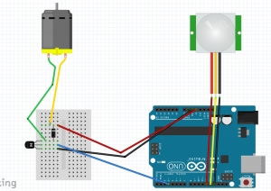
    2. The 4-wire jumper cable needs to be connected to the button. You have to connect them in the wires to the proper terminals on the button as seen in the diagram to the right.
    3. The servo needs to be modded so that it can lock the box you have chosen to use. This can be any of an unlimited amount of options, so just use the option that works best for you.

    Assembling the Box

    Finished Reverse Geocaching Box

    The Reverse Geocaching box can essentially be any type of box, so long as it can house all of the required electronics and a payload. It can be a wooden box, a metal box, an old lunch box, etc. There are a few things to keep in mind when creating a box. First, make sure that it can have the capability of being locked from the inside using the servo. Second, make sure you can cut out a portion of the box top in order to attach the LCD and button. Third, after all the electronics are inside the box, ensure that there is enough room for some type of payload or gift. And fourth, make sure that the Arduino is positioned so that it’s easy to plug into the computer without having to remove everything.

    Software

    Since this project runs off of an Arduino, you will need to download the [Arduino software] in order to load the Reverse Geocaching program onto it. It’s available for Windows Mac and Linux machines. Once you have it downloaded and installed, you can also [download an example program] for the Reverse Geocaching box from the Sundial website. Unzip it and then open up the extracted files into the Arduino program. You should see the code as well as some comments from Mikal Hart. The code by itself should work fine as is, but if we click the Verify button on the Arduino program, it’ll throw back errors regarding the PWMServo and tinyGPS libraries. Here’s how to fix those errors.

    Installing Libraries

    When it comes to code, libraries are a compiled set of commands that perform specific functions. For instance, if you want to control a servo but don’t want to write all the detailed code yourself, you can download a servo library and use that libraries pre-coded commands. This program requires two libraries to be installed: [PWMServo] and [TinyGPS].

    Both links to those libraries will provide a way to download them in zipped files. After you have them downloaded and unzipped, you want to move the entire library folder to the library folder of your Arduino installation, normally located in your Documents > Arduino folder path. After moving them, you will need to restart your Arduino program before any changes take effect. If you need more help on isntalling Arduino libraries, the Arduino website has a [good guide].

    Adjusting the lock settings

    Once restarted, you should be able to click Verify to verify the code and the code should pass. So now we can start customizing the code. The first thing to look at is the Open and Closed angles of the servo.

    static const int CLOSED_ANGLE = 90; 
    static const int OPEN_ANGLE = 165; 
    

    These will need to be adjusted so that your servo properly locks and unlocks the box. It will most likely take several tries to get this right. So make an adjustment, upload the code, let the code run through to see if it works, if not, adjust the angles more.

    Setting the location

    Immediately beneath the servo settings is the GPS coordinate settings.

    static const float DEST_LATITUDE = 48.8469;
    static const float DEST_LONGITUDE = -2.9986;
    

    The DEST_LATITUDE and DEST_LONGITUDE values tell where the box can be opened. How do you determine the latitude and longitude coordinates for your destination? The easiest way is by going to [Google Maps] and finding the destination location on the map. Then right click on that location and select What’s here. This will show the latitude and longitude coordinates respectively in the search bar at the top of the maps page. Then just copy those values to your code.

    Editing the LCD Messages

    The next bit of customizable code is about halfway down the program. It starts with the attempt counter and then displays a message in Msg(lcd, format.

      /* increment it with each run */
      ++attempt_counter;
    
      /* Copyright notice */
      Msg(lcd, "HELLO", "EXPLORER", 1500);
    
      /* Greeting */
      Msg(lcd, "Welcome", "to your", 2000);
      Msg(lcd, "puzzle", "box!", 2000);
    
      /* Game over? */
      if (attempt_counter >= DEF_ATTEMPT_MAX)
      {
        Msg(lcd, "Sorry!", "No more", 2000);
        Msg(lcd, "attempts", "allowed!", 2000);
        PowerOff();
      }
    

    Any of these items can be edited. The format is Msg(lcd, “‘First line'”, “Second line'”, delay time);. Keep in mind that each line on the screen is only 8 characters long.

    Adding Clues

    Along with displaying messages, you can also display different clues for each time the user presses the button. To do this, you want to create a new line of code similar to the code below. And you want the attempt_counter variable to be set equal to it’s corresponding clue. The attempt counter keeps track of how many times the user has pressed the button. If the user presses the button 1 time, it will show this code, which is the first clue. If you wanted to display a second clue, then you would set the attempt_counter to equal 2 and then change the display message to show the second clue.

      /* First Clue */
      if (attempt_counter == 1)
      {
        Msg(lcd, "Clue #1", "Bridge", 2000);
        PowerOff();
      }
    

    Uploading the code

    Once you have customized the code, the next step is to upload it to the Arduino. Assuming that the Arduino is already in your Reverse Geocaching Box, make sure that you have all batteries removed before connecting it to your computer. After you’ve connected it, go to Tools > Board and select your Arduino Board type and then go to Tools > Serial to select the USB port that it’s connected to. Now just click the Upload button on the program window and wait for it to upload to the Arduino. When it’s through, it should run through the code so you can see how it works. Then make any adjustments you need to and re-upload the code. After that, unplug the Arduino from your computer and insert the two AA batteries. Then insert your payload/gift, lock the box and give it to a friend!


    [/vc_column_text][/vc_tab][vc_tab title=”Important Links” tab_id=”1402753981900-3-108a6d-d37d76d3-94cefaff-ff2c”][vc_column_text]

    Help support my channel:

    1. Donate To My Patreon
    2. Follw Me On Google +
    3. Like Me On Facebook
    4. Follow Me On Twitter

    [/vc_column_text][/vc_tab][/vc_tabs][/vc_column][vc_column width=”1/3″][/vc_column][/vc_row]

  • HTML5 Photo Booth


    [vc_row][vc_column width=”2/3″][vc_separator][venera_framed_image content_type=”video” css_animation=”appear” frame_type=”browser” slider_engine=”flexslider” video_link=”https://www.youtube.com/watch?v=2sXkl3rR-yc” browser_url=”https://www.youtube.com/watch?v=2sXkl3rR-yc”][vc_separator][/vc_column][vc_column width=”1/3″][/vc_column][/vc_row][vc_row][vc_column width=”2/3″][vc_tabs][vc_tab title=”About This Project” tab_id=”1402713028-1-39e9a4-2f88123b-77946048-9294925e-bc34″][vc_column_text]

    HTML5 is ramping up to become a more and more robust markup language. So flex your code monkey muscles and lets make an HTML5 photo booth application.

    [/vc_column_text][vc_button title=”View Demo” target=”_self” icon=”none” size=”btn-huge” href=”http://www.tinkernut.com/demos/343_photobooth/photobooth.html”][/vc_tab][vc_tab title=”Code” tab_id=”1402753910272-3-8123b-77946048-9294925e-bc34″][vc_button title=”Download Code” target=”_blank” icon=”none” size=”btn-huge” href=”http://www.tinkernut.com/demos/343_photobooth/343_photobooth.zip”][vc_column_text]

    What you should already know

    Before starting this tutorial, it is assumed that you already know the basics of web development. This includes, HTML, CSS, Javascript, and HTML5. Without a basic understanding of these languages, it will be very difficult to understand the logic used to make this program work. So, as a prerequisite, it is recommended that you view these tutorials on the basics of web development before continuing.

    1. HTML Basics
    2. CSS Basics
    3. Javascript Basics
    4. HTML5 Basics

    Needed Tools

    Programming with web languages requires very little extra software. You only need three things:

    1. A text editor (I recommend Notepad ++)
    2. A compiler (Any web browser that supports HTML5 will do)
    3. A web server (A good free web server service is 000webhost)

    Demo and Download

    The code

    photobooth.html

    This is the full code that should be saved as photobooth.html and uploaded to your web server.

    <html>
         <head>
              <title>My Photo Booth</title>
         <head>
         <body>
              <center>
              <video id="webcam" width="200" height="200"></video>
              <br>
              <input type="button" id="snapPicture" value="Snap A Picture!" />
              <p> 
              <canvas id="capture" style="display:none;"></canvas>
              <img id="canvasImg" alt="right click to save">
              <script src = "script_photo.js"></script>
              </center>          
         </body>
    </html>


    script_photo.js

    This is the code for script_photo.js. This should be uploaded to your web server in the same direcotry as photobooth.html

    var photoButton = document.getElementById('snapPicture');
    photoButton.addEventListener('click', picCapture, false);
    
    navigator.getUserMedia ||
         (navigator.getUserMedia = navigator.mozGetUserMedia ||
         navigator.webkitGetUserMedia || navigator.msGetUserMedia);
    
    if (navigator.getUserMedia) {
              navigator.getUserMedia({video:true,audio:false}, onSuccess, onError);
         } else{
              alert('Your browser isn't supported');
    }
    
    function onSuccess(stream) {
         vidContainer = document.getElementById('webcam');
         var vidStream;
         if (window.webkitURL){
              vidStream = window.webkitURL.createObjectURL(stream);
              }else{
                   vidStream = stream;
         }
         vidContainer.autoplay = true;
         vidContainer.src = vidStream;
    
    }
    
    function onError(){
         alert('Houston, we have a problem');
    }
    
    function picCapture(){
         var picture = document.getElementById('capture'),
              context = picture.getContext('2d');
    
         picture.width = "600";
         picture.height = "400";
         context.drawImage(vidContainer, 0, 0, picture.width, picture.height);
    
         var dataURL = picture.toDataURL();
         document.getElementById('canvasImg').src = dataURL;
    }


    [/vc_column_text][/vc_tab][vc_tab title=”Important Links” tab_id=”1402753981900-3-10123b-77946048-9294925e-bc34″][vc_column_text]

    Important Links

    Help support my channel: http://www.patreon.com/tinkernut

    Follow Tinkernut!

    [/vc_column_text][/vc_tab][/vc_tabs][/vc_column][vc_column width=”1/3″][/vc_column][/vc_row]