Wow, the Raspberry Pi team is on a roll! The Pi 400, the Compute Module 4, and now a microcontroller?!?! Watch out Arduino, this could be the new gateway drug to electronics!
(more…)-
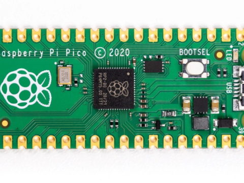
New Raspberry Pi Microcontroller Announced!!
// davisde // Uncategorized Tags: arduino, microcontroller, raspberrypi, tinkernut No Responses
-
Motion Controlled Ultrasonic Lamp
// davisde // Labs Tags: arduino, ultasonic 9 Responses
[highlight] THIS PAGE HAS MOVED TO: www.tinkernut.com/portfolio/motion-controlled-ultrasonic-lamp [/highlight]
-

Home Made Motion Activated Trash Can
// davisde // Labs Tags: arduino, ultrasonic 1 Response
[highlight] THIS PAGE HAS MOVED TO: http://clone.tinkernut.com/portfolio/motion-activated-trash-can/
[/highlight]
-
How To Make A Sonar Device
// davisde // Labs Tags: arduino, ultrasonic 2 Responses
[highlight] THIS PAGE HAS MOVED TO: http://clone.tinkernut.com/portfolio/make-sonar-device/
[/highlight]
-

Ultrasonic Madness
// davisde // DIY Projects Tags: arduino, ultrasonic 3 Responses
[vc_row][vc_column width=”2/3″][vc_separator][venera_framed_image content_type=”video” css_animation=”appear” frame_type=”browser” slider_engine=”flexslider” video_link=”https://www.youtube.com/watch?v=cV4MdQuRArE” browser_url=”https://www.youtube.com/watch?v=LssEe_xx3eI”][vc_separator][/vc_column][vc_column width=”1/3″][/vc_column][/vc_row][vc_row][vc_column width=”2/3″][vc_tabs][vc_tab title=”About This Project” tab_id=”1402713028-1-39e9a4-2f888a6d-d37d76d3-94ce5609-2f71″][vc_column_text]
Sound waves can be used for more than just making sound. Find out all the amazing things sound is capable of and make some cool projects that harness it’s power!
Click on the tabs to continue learning about ultrasound!
Here are some of the other cool projects you we’ll be creating:
[/vc_column_text][/vc_tab][vc_tab title=”Parts and Downloads” tab_id=”1402713028-2-39e9a4-2f888a6d-d37d76d3-94ce5609-2f71″][vc_button title=”Download Arduino Code” target=”_self” color=”btn-primary” icon=”none” size=”btn-huge” href=”http://www.tinkernut.com/demos/369_ultrasound/ultrasound_ruler_demo.zip”][vc_column_text]
Parts List
The prices really depend on what you would like to purchase. These are cheapest locations to purchase these items that I was able to find.
Part name Price Ultrasonic Module $2.40 Arduino Uno $8.75 Software Downloads
[/vc_column_text][/vc_tab][vc_tab title=”Continued Learning Links” tab_id=”1402753981900-3-108a6d-d37d76d3-94ce5609-2f71″][vc_column_text]
Awesome Ultrasound Projects and Experiments - MIT Sound Waves and Potato Chip Bags experiment
- uBeam Ultrasonic Charger
- Boris Smus – Ultrasonic Javascript Library (Emoticon Demo)
- Kate Murphey – “Quietnet” Ultrasonic Chat Client
Help support my channel: [/vc_column_text][/vc_tab][/vc_tabs][/vc_column][vc_column width=”1/3″][/vc_column][/vc_row]
-
Control An RC Car With A Smartphone
// davisde // DIY Projects Tags: android, arduino, bluetooth, control, create, electronics, motors, project, radio, smartphone 6 Responses
[tabby title=”Video Walkthrough”]
Learn the basics of controlling objects with your Smartphone through Bluetooth!
[tabby title=”Parts List”]
Acquiring the Parts Here’s what you will need:- A Bluetooth Capable Smartphone (I’ll be using an Android).
- An Arduino ($10.99)
- An Arduino Bluetooth Module ($6.45)
- An RC Car (this is the one I used) ($5.00 – $30.00)
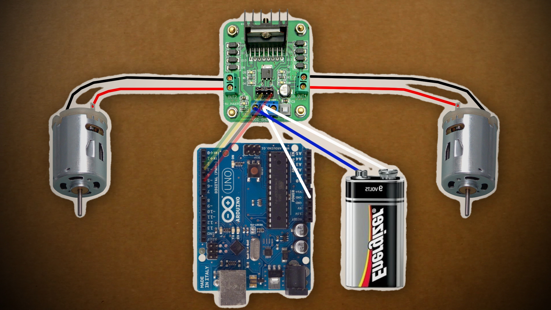
- An H-Bridge motor controller ($9.69)
- A Wires ($4.20)
- A 9v Battery ($2.00)
TOTAL COST: ~$30.00
[tabby title=”Step 1″]
Adding Bluetooth to the Arduino - To get started on adding bluetooth to the Arduino, you can watch my Arduino Bluetooth Basics Tutorial
-
For a wiring diagram, you can reference my Fritzing sketch. (You need to download Fritzing
in order t. view this.)
[tabby title=”Step 2″]
Software
Android
- To find your bluetooth’s MAC address, a good program to use is called Ardudroid on the Google Play store.
- To control the car, Tolik777 has created a great app that you can download from here and install on your Anrdoid device.
Arduino
- The first thing you need to to is download the Arduino software for your computer.
- Then you need to copy this code to a new sketch and upload it to your Arduino device. Code provided by
#include "EEPROM.h"

#define D1 2          // direction of motor rotation 1
#define M1 3          // PWM left motor
#define D2 4          // direction of motor rotation 2
#define M2 5          // PWM right motor
#define HORN 13       // additional channel 1
//#define autoOFF 2500  // milliseconds after which the robot stops when the connection

#define cmdL 'L'      // UART-command for left motor
#define cmdR 'R'      // UART-command for right motor
#define cmdH 'H'      // UART-command for additional channel (for example Horn)
#define cmdF 'F'      // UART-command for EEPROM operation
#define cmdr 'r'      // UART-command for EEPROM operation (read)
#define cmdw 'w'      // UART-command for EEPROM operation (write)

char incomingByte;    // incoming data

char L_Data[4];       // array data for left motor
byte L_index = 0;     // index of array L
char R_Data[4];       // array data for right motor
byte R_index = 0;     // index of array R
char H_Data[1];       // array data for additional channel
byte H_index = 0;     // index of array H
char F_Data[8];       // array data for  EEPROM
byte F_index = 0;     // index of array F
char command;         // command

unsigned long currentTime, lastTimeCommand, autoOFF;

void setup() {
  Serial.begin(9600);       // initialization UART
  pinMode(HORN, OUTPUT);    // additional channel
  pinMode(D1, OUTPUT);      // output for motor rotation
  pinMode(D2, OUTPUT);      // output for motor rotation
  /*EEPROM.write(0,255);
  EEPROM.write(1,255);
  EEPROM.write(2,255);
  EEPROM.write(3,255);*/
  timer_init();             // initialization software timer
}

void timer_init() {
  uint8_t sw_autoOFF = EEPROM.read(0);   // read EEPROM "is activated or not stopping the car when losing connection"
  if(sw_autoOFF == '1'){                 // if activated
    char var_Data[3];
    var_Data[0] = EEPROM.read(1);
    var_Data[1] = EEPROM.read(2);
    var_Data[2] = EEPROM.read(3);
    autoOFF = atoi(var_Data)*100;        // variable autoOFF ms
  }
  else if(sw_autoOFF == '0'){
    autoOFF = 999999;
  }
  else if(sw_autoOFF == 255){
    autoOFF = 2500;                      // if the EEPROM is blank, dafault value is 2.5 sec
  }
  currentTime = millis();                // read the time elapsed since application start
}

void loop() {
  if (Serial.available() > 0) {          // if received UART data
    incomingByte = Serial.read();        // raed byte
    if(incomingByte == cmdL) {           // if received data for left motor L
      command = cmdL;                    // current command
      memset(L_Data,0,sizeof(L_Data));   // clear array
      L_index = 0;                       // resetting array index
    }
    else if(incomingByte == cmdR) {      // if received data for left motor R
      command = cmdR;
      memset(R_Data,0,sizeof(R_Data));
      R_index = 0;
    }
    else if(incomingByte == cmdH) {      // if received data for additional channel
      command = cmdH;
      memset(H_Data,0,sizeof(H_Data));
      H_index = 0;
    }
    else if(incomingByte == cmdF) {      // if received data for EEPROM op
      command = cmdF;
      memset(F_Data,0,sizeof(F_Data));
      F_index = 0;
    }
    else if(incomingByte == '\r') command = 'e';   // end of line
    else if(incomingByte == '\t') command = 't';   // end of line for EEPROM op

    if(command == cmdL && incomingByte != cmdL){
      L_Data[L_index] = incomingByte;              // store each byte in the array
      L_index++;                                   // increment array index
    }
    else if(command == cmdR && incomingByte != cmdR){
      R_Data[R_index] = incomingByte;
      R_index++;
    }
    else if(command == cmdH && incomingByte != cmdH){
      H_Data[H_index] = incomingByte;
      H_index++;
    }
    else if(command == cmdF && incomingByte != cmdF){
      F_Data[F_index] = incomingByte;
      F_index++;
    }
    else if(command == 'e'){                       // if we take the line end
      Control4WD(atoi(L_Data),atoi(R_Data),atoi(H_Data));
      delay(10);
    }
    else if(command == 't'){                       // if we take the EEPROM line end
      Flash_Op(F_Data[0],F_Data[1],F_Data[2],F_Data[3],F_Data[4]);
    }
    lastTimeCommand = millis();                    // read the time elapsed since application start
  }
  if(millis() >= (lastTimeCommand + autoOFF)){     // compare the current timer with variable lastTimeCommand + autoOFF
    Control4WD(0,0,0);                             // stop the car
  }
}

void Control4WD(int mLeft, int mRight, uint8_t Horn){

  bool directionL, directionR;      // direction of motor rotation L298N
  byte valueL, valueR;              // PWM M1, M2 (0-255)

  if(mLeft > 0){
    valueL = mLeft;
    directionL = 0;
  }
  else if(mLeft < 0){
    valueL = 255 - abs(mLeft);
    directionL = 1;
  }
  else {
    directionL = 0;
    valueL = 0;
  }

  if(mRight > 0){
    valueR = mRight;
    directionR = 0;
  }
  else if(mRight < 0){
    valueR = 255 - abs(mRight);
    directionR = 1;
  }
  else {
    directionR = 0;
    valueR = 0;
  }

  analogWrite(M1, valueL);            // set speed for left motor
  analogWrite(M2, valueR);            // set speed for right motor
  digitalWrite(D1, directionL);       // set direction of left motor rotation
  digitalWrite(D2, directionR);       // set direction of right motor rotation

  digitalWrite(HORN, Horn);           // additional channel
}

void Flash_Op(char FCMD, uint8_t z1, uint8_t z2, uint8_t z3, uint8_t z4){

  if(FCMD == cmdr){           // if EEPROM data read command
    Serial.print("FData:");       // send EEPROM data
    Serial.write(EEPROM.read(0));     // read value from the memory with 0 address and print it to UART
    Serial.write(EEPROM.read(1));
    Serial.write(EEPROM.read(2));
    Serial.write(EEPROM.read(3));
    Serial.print("\r\n");         // mark the end of the transmission of data EEPROM
  }
  else if(FCMD == cmdw){          // if EEPROM data write command
    EEPROM.write(0,z1);               // z1 record to a memory with 0 address
    EEPROM.write(1,z2);
    EEPROM.write(2,z3);
    EEPROM.write(3,z4);
    timer_init();             // reinitialize the timer
    Serial.print("FWOK\r\n");         // send a message that the data is successfully written to EEPROM
  }
}
[tabby title="Links"]
Follow Tinkernut!
Google +
Facebook
Twitter
[tabbyending] -

How To Make A Reverse Geocaching Puzzle Box
// davisde // DIY Projects Tags: arduino 2 Responses
[vc_row][vc_column width=”2/3″][vc_separator][venera_framed_image content_type=”video” css_animation=”appear” frame_type=”browser” slider_engine=”flexslider” video_link=”https://www.youtube.com/watch?v=qhX3N6YhPRM” browser_url=”https://www.youtube.com/watch?v=qhX3N6YhPRM”][vc_separator][/vc_column][vc_column width=”1/3″][/vc_column][/vc_row][vc_row][vc_column width=”2/3″][vc_tabs][vc_tab title=”About This Project” tab_id=”1402713028-1-39e9a4-2f888a6d-d37d76d3-94cefaff-ff2c”][vc_column_text]
A “[Reverse Geocaching Puzzle Box]” is an electronic puzzle box developed by [Mikal Hart]. It runs primarily off of an Arduino along with a handful of peripherals. This episode covers how to acquire and assemble the parts needed for the Puzzle Box as well as customizing and installing the software to run it.
If you’ve never heard of [Geocaching], it’s an outdoor activity where participants use a GPS to find and hide containers known as “Geocaches”. These containers normally contain some kind of trinket or memorabilia. So as you can imagine, “Reverse Geocaching” is where you have the container with you the whole time, and you have to take it to a specific location GPS coordinates in order to open it. In essence, it stays locked unless you’re standing in the right place.
[/vc_column_text][/vc_tab][vc_tab title=”Parts and Downloads” tab_id=”1402713028-2-39e9a4-2f888a6d-d37d76d3-94cefaff-ff2c”][vc_column_text]
Parts List
The price of this project depends on what you already have available and where you purchase your items. All in all, you can probably complete this project for less than $100. I’ve listed all of the required parts below as well as some cheap places to purchase them.
Reverse Geocaching Shield Version 1.0
Part name Price Some type of Box $0 GPS Adapter $29 LCD Screen (2 x 8) $6 Push Button $4 Small Servo $4 Arduino Uno $10 Reverse Geocaching Shield Kit $32 Battery Terminal $2 8 x 2 Ribbon Cable $4 4 wire jumper cable $3 [/vc_column_text][/vc_tab][vc_tab title=”Assembly” tab_id=”1402753910272-3-88a6d-d37d76d3-94cefaff-ff2c”][vc_column_text]
Building The Hardware
Putting together all of the electronics to make this box work requires a soldering iron and some basic soldering skills. Assembling the box could require a [Dremel], or other wood working tool. The core of this project revolves around the Arduino and the Reverse Gecaching shield. A “ shield” is essentially an electronics board that connects on top of an Arduino and extends it’s functionality. In this case, the RG shield easily connects the Arduino to the GPS, button, LCD and servo. Essentially 75% of the build involves assembling the RG shield.
Assembing the RG Shield
If you purchased the RG Shield kit, then as long as you have soldering skills, this should be pretty easy.


Fully assembled RG shield + Arduino
- Break the header (straight) pins so that they line up with the pins on the Arduino. Go ahead and place them into the Arduino with the long ends down.
- Place the RG Shield so on top of the Arduino so that the header pins slide into place and then solder the top of each pin to the shield.
- Break off 2 rows of 8 header pins and solder them into the corresponding holes onto the bottom of the RG board.
- In version 1.0 of the shield, there are 3 electronic components: 2 capacitors and 1 resistor. Match each component to it’s corresponding shape on the RG shield and solder them into place.
- Break off 4 right-angle pins and solder them, facing outward, to the bottom of the corresponding holes in the RG board.
- Break off another 3 right-angle pins and solder them, facing outward, to the bottom of the corresponding holes in the RG board.
- Find the GPS connector and position it where it belongs on the RG board and very carefully solder it into place, taking extra care not to solder the connector pins together.
- Solder some header pins to the top of the RG board where the 5v boost belongs.
- Place the 5v boost on top of those header pins and solder it into place.
- Solder some header pins to the top of the RG board where the regulator switch belongs.
- Place the regulator switch on top of those header pins and solder them into place.
- Lastly, solder the red and black wires from the battery terminal to the RG board. Ensure that the + and – wires are in the correct holes.
Other Miscellaneous Electronic Assembly

Button Wiring Diagram
- The LCD screen requires minimal assembly. Break off 2 rows of 8 header pins and solder them to the corresponding holes on the LCD screen.
- The 4-wire jumper cable needs to be connected to the button. You have to connect them in the wires to the proper terminals on the button as seen in the diagram to the right.
- The servo needs to be modded so that it can lock the box you have chosen to use. This can be any of an unlimited amount of options, so just use the option that works best for you.
Assembling the Box

Finished Reverse Geocaching Box
The Reverse Geocaching box can essentially be any type of box, so long as it can house all of the required electronics and a payload. It can be a wooden box, a metal box, an old lunch box, etc. There are a few things to keep in mind when creating a box. First, make sure that it can have the capability of being locked from the inside using the servo. Second, make sure you can cut out a portion of the box top in order to attach the LCD and button. Third, after all the electronics are inside the box, ensure that there is enough room for some type of payload or gift. And fourth, make sure that the Arduino is positioned so that it’s easy to plug into the computer without having to remove everything.
Software
Since this project runs off of an Arduino, you will need to download the [Arduino software] in order to load the Reverse Geocaching program onto it. It’s available for Windows Mac and Linux machines. Once you have it downloaded and installed, you can also [download an example program] for the Reverse Geocaching box from the Sundial website. Unzip it and then open up the extracted files into the Arduino program. You should see the code as well as some comments from Mikal Hart. The code by itself should work fine as is, but if we click the Verify button on the Arduino program, it’ll throw back errors regarding the PWMServo and tinyGPS libraries. Here’s how to fix those errors.
Installing Libraries
When it comes to code, libraries are a compiled set of commands that perform specific functions. For instance, if you want to control a servo but don’t want to write all the detailed code yourself, you can download a servo library and use that libraries pre-coded commands. This program requires two libraries to be installed: [PWMServo] and [TinyGPS].
Both links to those libraries will provide a way to download them in zipped files. After you have them downloaded and unzipped, you want to move the entire library folder to the library folder of your Arduino installation, normally located in your Documents > Arduino folder path. After moving them, you will need to restart your Arduino program before any changes take effect. If you need more help on isntalling Arduino libraries, the Arduino website has a [good guide].
Adjusting the lock settings
Once restarted, you should be able to click Verify to verify the code and the code should pass. So now we can start customizing the code. The first thing to look at is the Open and Closed angles of the servo.
static const int CLOSED_ANGLE = 90;
static const int OPEN_ANGLE = 165;
These will need to be adjusted so that your servo properly locks and unlocks the box. It will most likely take several tries to get this right. So make an adjustment, upload the code, let the code run through to see if it works, if not, adjust the angles more.
Setting the location
Immediately beneath the servo settings is the GPS coordinate settings.
static const float DEST_LATITUDE = 48.8469;
static const float DEST_LONGITUDE = -2.9986;
The DEST_LATITUDE and DEST_LONGITUDE values tell where the box can be opened. How do you determine the latitude and longitude coordinates for your destination? The easiest way is by going to [Google Maps] and finding the destination location on the map. Then right click on that location and select What’s here. This will show the latitude and longitude coordinates respectively in the search bar at the top of the maps page. Then just copy those values to your code.
Editing the LCD Messages
The next bit of customizable code is about halfway down the program. It starts with the attempt counter and then displays a message in Msg(lcd, format.
  /* increment it with each run */
  ++attempt_counter;

  /* Copyright notice */
  Msg(lcd, "HELLO", "EXPLORER", 1500);

  /* Greeting */
  Msg(lcd, "Welcome", "to your", 2000);
  Msg(lcd, "puzzle", "box!", 2000);

  /* Game over? */
  if (attempt_counter >= DEF_ATTEMPT_MAX)
  {
    Msg(lcd, "Sorry!", "No more", 2000);
    Msg(lcd, "attempts", "allowed!", 2000);
    PowerOff();
  }
Any of these items can be edited. The format is Msg(lcd, “‘First line'”, “Second line'”, delay time);. Keep in mind that each line on the screen is only 8 characters long.
Adding Clues
Along with displaying messages, you can also display different clues for each time the user presses the button. To do this, you want to create a new line of code similar to the code below. And you want the attempt_counter variable to be set equal to it’s corresponding clue. The attempt counter keeps track of how many times the user has pressed the button. If the user presses the button 1 time, it will show this code, which is the first clue. If you wanted to display a second clue, then you would set the attempt_counter to equal 2 and then change the display message to show the second clue.
  /* First Clue */
  if (attempt_counter == 1)
  {
    Msg(lcd, "Clue #1", "Bridge", 2000);
    PowerOff();
  }
Uploading the code
Once you have customized the code, the next step is to upload it to the Arduino. Assuming that the Arduino is already in your Reverse Geocaching Box, make sure that you have all batteries removed before connecting it to your computer. After you’ve connected it, go to Tools > Board and select your Arduino Board type and then go to Tools > Serial to select the USB port that it’s connected to. Now just click the Upload button on the program window and wait for it to upload to the Arduino. When it’s through, it should run through the code so you can see how it works. Then make any adjustments you need to and re-upload the code. After that, unplug the Arduino from your computer and insert the two AA batteries. Then insert your payload/gift, lock the box and give it to a friend!
[/vc_column_text][/vc_tab][vc_tab title=”Important Links” tab_id=”1402753981900-3-108a6d-d37d76d3-94cefaff-ff2c”][vc_column_text]
Help support my channel: [/vc_column_text][/vc_tab][/vc_tabs][/vc_column][vc_column width=”1/3″][/vc_column][/vc_row]
-

Arduino Basics: Servos & Potentiometers
// davisde // Computer Hardware Tags: arduino, basics, beginner, beginners, electronics, hacker, hardware, motors, resistor, tinkernut, tips, tricks, tutorial, variable, webcam, weekend 3 Responses
Learn how to control a servo using an Arduino and learn the basics of variable resistors. For more Arduino tutorials, visit my Arduino tutorial playlist. -

Arduino Basics: Input Control
// davisde // All Projects, Computer Hardware Tags: arduino, basic, basics, beginner, control, hardware, project, resistor, simple, user 4 Responses
Learn how to use an arduino to control objects using physical input, such as a button. Below are links to more Arduino beginner tutorials:
Arduino Playlist –
Arduino Beginners Guide – http://www.youtube.com/watch?v=PWKYYJu4yVw
-

Learn How To Use An Arduino
// davisde // Computer Hardware Tags: arduino 7 Responses
[vc_row][vc_column width=”2/3″][vc_separator][venera_framed_image content_type=”video” css_animation=”appear” frame_type=”browser” slider_engine=”flexslider” video_link=”https://www.youtube.com/watch?v=PWKYYJu4yVw” browser_url=”https://www.youtube.com/watch?v=PWKYYJu4yVw”][vc_separator][/vc_column][vc_column width=”1/3″][/vc_column][/vc_row][vc_row][vc_column width=”2/3″][vc_tabs][vc_tab title=”About This Project” tab_id=”1402713028-1-39e9a4-2f88123b-77946048-92948c2b-0e6b”][vc_column_text]
The easiest way to make and control your own electronics is through a device called an “Arduino”. This video shows you the basics of getting started with it.
[/vc_column_text][/vc_tab][vc_tab title=”Parts and Code” tab_id=”1402753910272-3-8123b-77946048-92948c2b-0e6b”][vc_button title=”Download The Arduino Software” target=”_blank” icon=”none” size=”btn-huge” href=”http://arduino.cc/en/Main/Software”][vc_column_text]
Obtaining An Arduino
Arduino’s can be purchased online at varying prices. Amazon or Ebay will vary greatly in prices. The price also depends on the version of Arduino that you purchase. The current version is the Uno and the older version is the Duemilanove. Other types of Arduino exist as well, such as an Arduino that you can build yourself, Arduino Nano, Lilypad, Arduino BT and a lot more.
Version Price Arduino Uno $29.96 Installing the Software
You can download the Arduino software from here. It’s available for Windows, Mac and Linux. It downloads in a zip file, so you will need archiving software such as 7-zip to unzip it. Then you will need to just click on the “Arduino” program icon to launch the program.

Arduino Uno board
The first thing you want to do is check to make sure the program is set to match the Arduino board that you are using. You can find out the type of board you have by looking on either the top or the bottom of the board. Then go to Tools>Boards from the menu and select your board.
Also you need to make sure the correct serial port is selected. This section is also accessed from the Tools menu. If the option is greyed out, then that means your Arduino board is not connected properly. You can find some common troubleshooting techniques below. For most new computers that only have one Arduino connected to them, there will most likely only be one serial port to select.
Creating A Program
The Arduino uses C/C++ programming language, so if you’re familiar with those languages you’re already way ahead of the curve. The Arduino program basically allows you to write a program, upload it to your Arduino device and save it for later use. The programs tell the Arduino what to do, how to control things, what information to retrieve, etc. You can find lots of sample programs by going to File > Examples. The sample program used in the video can also be found at File > Examples > 01.Basics > Blink. The final code can be seen here:
int led = 13;

void setup() {
  pinMode(led, OUTPUT);
}

void loop() {
  digitalWrite(led, HIGH);
  delay(1000);
  digitalWrite(led, LOW);
  delay(1000);
}
As you become more advanced with creating programs and adding devices, you will need to start using different Arduino libraries. The make is easy to extend the functionality of the Arduino in amazing ways.
Connecting Devices to the Arduino
The sky is the limit when it comes to what can be connected to the Arduino. But you must know how to connect them. There are lots of input/output ports on the Arduino. Some are analog and some are digital. Please refer to the online documentation to know which pins are best for your project.
Powering the Arduino
The Arduino runs off of 5 volts, so whenever it’s connected to your computer via USB, it can power itself. If you wanted to run it separately from your computer, then you would need to supply it with 5 volts via a battery pack or by wiring 5 volts of current through the Arduino’s power pins.
Troubleshooting
Serial Port option is greyed out
This generally means that your Arduino board either is not connected properly or not installed properly. Check your USB cord and the connection to make sure that it is connected properly. On Windows 7 and some Vista machines, you will need to install the drivers for the Arduino before it works. To do this, open up your Device Manager (Start>Search>”Device Manager”) and look for any device that has an exclamation point or question mark beside it. Right click on that device and choose “Update Driver”. Then browse to the “drivers” folder in your Arduino installation folder. After clicking next, it should install the drivers.
Program does not upload to Arduino
There three main reasons this will happen:
- The board is not connected.
- The board is not installed correctly (see above).
- The board you are using is different from the board selected in Tools > Boards.
The LED does not blink
Please check the previous troubleshooting questions to see if they resolve this problem before continuing. If it still is not working, then the LED is not connected properly. Make sure the positive leg (the longer LED leg) is connected to port 13 and the negative leg (on the same side as the flat part of the LED) is connected to GND. It will not work in any other ports due to port 13 being the only one that has a built-in resistor.
[/vc_column_text][/vc_tab][vc_tab title=”Important Links” tab_id=”1402753981900-3-10123b-77946048-92948c2b-0e6b”][vc_column_text] Help support my channel: http://www.patreon.com/tinkernut Follow Tinkernut! Google + Facebook Twitter [/vc_column_text][/vc_tab][/vc_tabs][/vc_column][vc_column width=”1/3″][/vc_column][/vc_row]