[button type=”btn_small” url=”http://tinkernut.com/dvYN6″ target=”” button_color_fon=”#36bf00″ ]FOLLOW THIS PROJECT[/button]
The Raspberry Pi Zero W is an amazing miniature computer piece of technology. I want to turn it into an epic portable Spotify radio that displays visuals such as Album Art. So in this new series called “Tinkernut Workbench”, I show you step by step what it takes to build a product from the ground up.
[slogan h1=”Important Links”]
[ox_list type=”ox_list_animated”]
[/ox_list]
[/slogan]
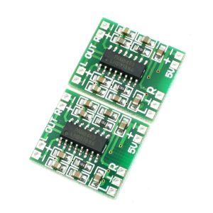
Now that we have a sound output from the Raspberry Pi, it’s not much more than a faint signal. In the example above, I used powered speakers with a built in amplifier to hear the music, but since the intent is to make my own radio, I’m looking for a more home brew method of amplifying sound. However, let me be preface that saying that I don’t know if making an amp from scratch is the best solution for this project. There are much better modules and circuits out there that can do the job much better than anything I can make, and for a fraction of the cost. So here are some of the pre-made options I’ve been considering:
[ox_list type=”ox_list_simple”]
- PAM8403 Amplifier Board
- MAX98357A Amplifier Board
- Just use the board from the cheap speakers I already have.
[/ox_list]
Just in case your curious and wanted to make your own amplifier from scratch, below are the steps to do so. However, the results are very poor. But I’ll show you the steps anyway just to learn the process and have the knowledge. If you don’t care about the knowledge, then just go with one of the options above and skip this section. Otherwise, here’s the steps it takes to make an amp.
The most common way of amplifying audio is using an Operational Amplifier (Op-Amp) chip. The one that I had in my box of electronic components is the LM386. Considering that it’s about $3 for a pack of 5, it’s not a bad investment.
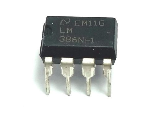
LM386 Signal Amplifier
Well, I’ve got the chip…but how do I use it? Consulting my BFF Google, I found several simple example circuits and resources for getting things connected. The best resource by far is over at CircuitBasics.com, where they discuss different types of circuits ranging from easy to complex, and the benefits of each. But the one I ended up using was this guide, simply because it was simple and had decent quality results.
-
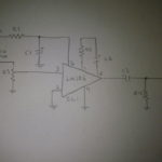
- Sketched Circuit
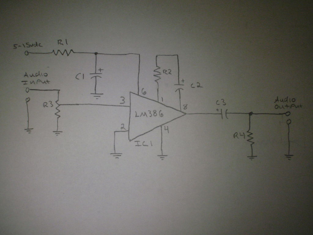
-
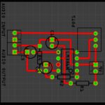
- Routed Circuit
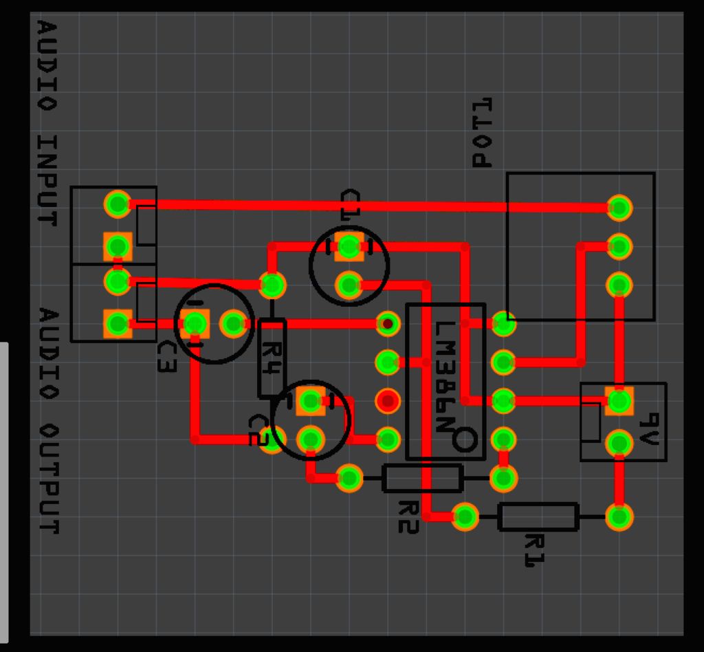
Now that I’ve got a circuit to go by, time to gather the components to make it work. Here’s what we’ll need:
[ox_list type=”ox_list_simple”]
- 1 x 10uf Capacitor
- 2 x 220uf Capacitors
- 1 x 10k Ohm potentiometer
- 1 x 1k Ohm resistor
- 2 x 10 Ohm resistors
- 9v Battery
- Speaker
[/ox_list]
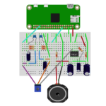
Using a breadboard (at first), I connected all of the components as per the circuit diagram above. The final circuit looked a little something like this:
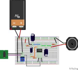
The audio input (green square on the left) is where I connected the output from the audio output shield we made in step 3. it’s all powered by a 9v battery. Turning the potentiometer (blue box in diagram) will adjust the volume of the sound. Playing the sample sound (aplay /usr/share/sounds/alsa/Front_Center.wav) should produce an amplified sound through the speaker (with possibly a little static). Below is what my actual breadboard looked like.
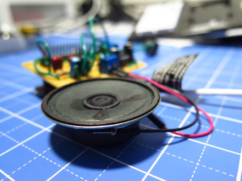
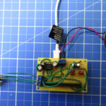
Now the tricky part here is to combine this amp onto the audio output circuit board we just created. And another tricky portion of that is to integrate the power that powers the amp with the output power from the Raspberry Pi. I ended up having to just create a whole new circuit board with everything on it. And to be honest, the results were less than spectacular…probably due to the fact that the Pi wasn’t providing enough power to the amp.
With the amp built and the final results lacking, I think I’ll be going with the PAM8403 amplifier board and just saving myself the headache.
Leave a Reply